EchoPilot PWM Pinout
EchoPilot PWM Breakout Board Pinout
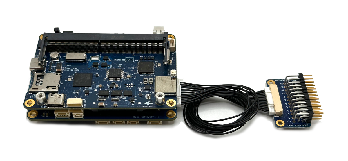
EchoPilot Carrier Board Connector (J1)
This connector is used along with the provided cable to connect to J20 on the Carrier Board.
Connector: J1, Part Number: SM14B-SRSS-TB(LF)(SN)
Mating Connector: SHR-14V-S-B
| Pin Number | Direction | Voltage | Pin Description |
|---|---|---|---|
| PIN 1 | Pwr | GND | GND |
| PIN 2 | Pwr | +5V | +VServo Sense |
| PIN 3 | O | +3.3V | FMU (AUX) PWM CH4 |
| PIN 4 | O | +3.3V | FMU (AUX) PWM CH3 |
| PIN 5 | O | +3.3V | FMU (AUX) PWM CH2 |
| PIN 6 | O | +3.3V | FMU (AUX) PWM CH1 |
| PIN 7 | O | +3.3V | IO (MAIN) PWM CH8 |
| PIN 8 | O | +3.3V | IO (MAIN) PWM CH7 |
| PIN 9 | O | +3.3V | IO (MAIN) PWM CH6 |
| PIN 10 | O | +3.3V | IO (MAIN) PWM CH5 |
| PIN 11 | O | +3.3V | IO (MAIN) PWM CH4 |
| PIN 12 | O | +3.3V | IO (MAIN) PWM CH3 |
| PIN 13 | O | +3.3V | IO (MAIN) PWM CH2 |
| PIN 14 | O | +3.3V | IO (MAIN) PWM CH1 |
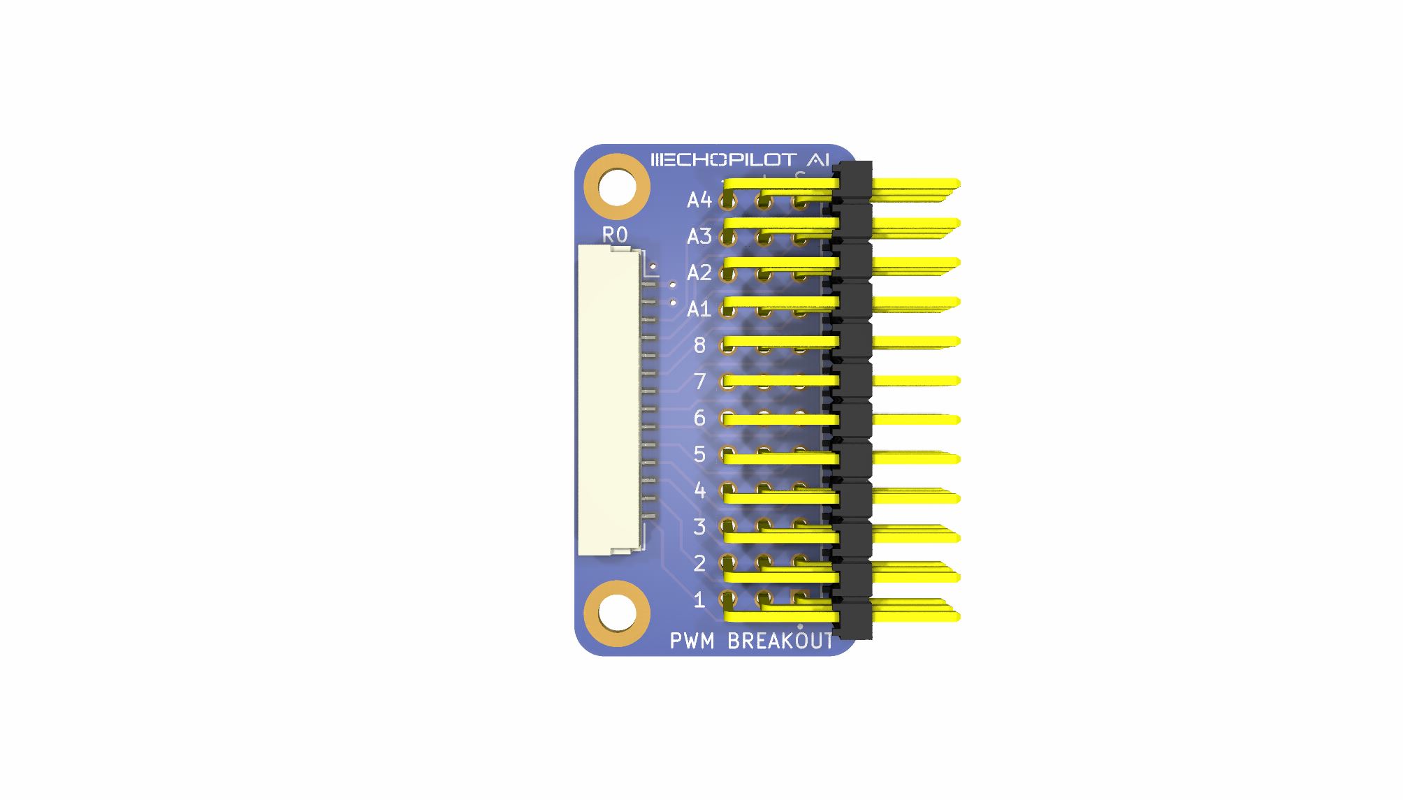
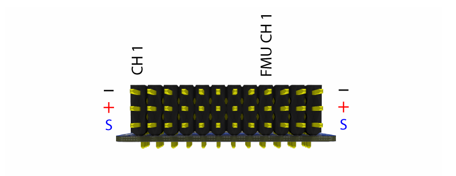
Header PWM Outputs
This header is used to connect to Futaba-style servo connectors. The PWM outputs are broken up into two groups. To understand why, consider that the autopilot is based on two separate ICs: a primary controller (often referred to as "the" FMU) and an IO controller (IOMCU). The IOMCU provides the PWM output to MAIN CH1 - CH8, while the FMU directly handles AUX CH1 - CH4. The naming convention of MAIN and AUX come from previous Pixhawk designs, where the IOMCU outputs are historically (confusingly?) labeled "MAIN." The outputs directly from the FMU are historically named "AUX." At this point you might be asking yourself "why do we need to ICs, this seems to just add confusion?" There are two reasons why the EchoPilot uses an IOMCU (many autopilots do not): 1. It allows us to support up to 14 PWM outputs and 2. It provides a level of safety and redundancy because the IOMCU can allow core functionality (RC Control) even if the primary FMU fails or crashes.
For most applications either group of outputs can be used. However, one important consideration between "MAIN" and "AUX" outputs are if you are using DShot if your system. DShot outputs are only supported by the FMU, therefore on the EchoPilot AI only the AUX outputs support DShot. With the stock Carrier board and PWM breakout board, 4 AUX outputs are available. The EchoPilotAI supports up to 6 AUX outputs via custom carrier board design.
Warning
The middle ("+") pin is bussed together, allowing you to distribute your +VServo voltage. The EchoPilot AI does NOT provide +VServo voltage, this must be supplied by an external regulator, BEC, etc. Typically +VServo is provided by an Electronic Speed Controller (ESC) in the system.
Connector: J2, Part Number: TSW-112-08-G-T-RA_1
Mating Connector: Standard 0.1" spacing servo/esc Futaba style
STEP File Download
EchoPilot AI PWM Breakout Board 3D model (STEP) File Download (right click, save link as)