EchoPilot Carrier Pinout
The Carrier Board is open-source, please visit the echopilot_ai_carrier repository. While you may refer to the pinout information below, also feel free to examine the pdf schematic or the full design in Kicad 7.0+.
Carrier Board Schematic
A full schematic of the carrier board is available: PDF schematic
Top Side Carrier Board
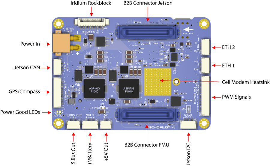
Iridium Rockblock 9603 (J10)
This connector is for connection to a Rockblock Iridium 9603 modem. A straight-through cable with Molex 0510211000 connectors may be used.
Connector: J10, Part Number: 0532617010
Mating Connector: 0510211000
| Pin Number | Direction | Voltage | Pin Desription |
|---|---|---|---|
| 1 | Pwr | GND | GND |
| 2 | NA | NA | NC |
| 3 | Pwr OUT | +5V | +5V_OUT33 |
| 4 | O | 3.3V | Iridium On/Off |
| 5 | I | 3.3V | TX (from modem's perspective) |
| 6 | I | 3.3V | Iridium Ring |
| 7 | I | 3.3V | Iridium Network Available |
| 8 | NA | NA | NC |
| 9 | NA | NA | NC |
| 10 | O | 3.3V | RX (from modem's perspective) |
Note
Custom software is required to implement Iridium SBD communications. Pinmux modifications may be required pending how a software implementation leverages the Iridium modem IO.
Ethernet 2 (J9)
This connector is used for Ethernet (100 Mbps to the Jetson). This is connected to a KSZ8795CLXIC 4-port ethernet switch onboard the EchoPilot AI.
Note
The magnetics for Ethernet 2 are onboard the Carrier Board.
Connector: J9, Part Number: SM04B-GHS-TB(LF)(SN)
Mating Connector: GHR-04V-S
| Pin Number | Direction | Voltage | Pin Description |
|---|---|---|---|
| 1 | IO | Diff Signal | Rx+ |
| 2 | IO | Diff Signal | Rx- |
| 3 | IO | Diff Signal | Tx+ |
| 4 | IO | Diff Signal | Tx- |
Ethernet 1 (J15)
This connector is used for Ethernet (100 Mbps to the Jetson). This is connected to a KSZ8795CLXIC 4-port ethernet switch onboard the EchoPilot AI.
Note
The magnetics for Ethernet 1 are onboard the Carrier Board.
Connector: J15, Part Number: SM04B-GHS-TB(LF)(SN)
Mating Connector: GHR-04V-S
| Pin Number | Direction | Voltage | Pin Description |
|---|---|---|---|
| 1 | IO | Diff Signal | Rx+ |
| 2 | IO | Diff Signal | Rx- |
| 3 | IO | Diff Signal | Tx+ |
| 4 | IO | Diff Signal | Tx- |
Board to Board Jetson (J5)
This connector handles the Jetson-related board to board signals. It connects to the EchoPilot AI board.
Connector: J5, Part Number: FX23L-80P-0.5SV10
Mating Connector: FX23L-80S-0.5SV
| Pin Number | Direction | Voltage | Pin Desription |
|---|---|---|---|
| 1 | IO | Diff Signal | Jetson CAN+ |
| 2 | IO | Diff Signal | Jetson CAN- |
| 3 | Pwr | GND | GND |
| 4 | IO | 1.8V | CAM0_SDA0 |
| 5 | IO | 1.8V | CAM0_SCL0 |
| 6 | IO | 1.8V | CAM0_MCLK |
| 7 | IO | 1.8V | CAM0_GPIO |
| 8 | Pwr | GND | GND |
| 9 | IO | Diff Signal | CAM0_D1+ |
| 10 | IO | Diff Signal | CAM0_D1- |
| 11 | Pwr | GND | GND |
| 12 | IO | Diff Signal | CAM0_CLK+ |
| 13 | IO | Diff Signal | CAM0_CLK- |
| 14 | Pwr | GND | GND |
| 15 | IO | Diff Signal | CAM0_D0+ |
| 16 | IO | Diff Signal | CAM0_D0- |
| 17 | Pwr | GND | GND |
| 18 | IO | 1.8V | CAM1_SDA0 |
| 19 | IO | 1.8V | CAM1_SCL0 |
| 20 | IO | 1.8V | CAM1_MCLK |
| 21 | IO | 1.8V | CAM1_GPIO |
| 22 | Pwr | GND | GND |
| 23 | IO | Diff Signal | CAM1_D1+ |
| 24 | IO | Diff Signal | CAM1_D1- |
| 25 | Pwr | GND | GND |
| 26 | IO | Diff Signal | CAM1_CLK+ |
| 27 | IO | Diff Signal | CAM1_CLK- |
| 28 | Pwr | GND | GND |
| 29 | IO | Diff Signal | CAM1_D0+ |
| 30 | IO | Diff Signal | CAM1_D0- |
| 31 | Pwr | GND | GND |
| 32 | IO | Diff Signal | CAM0_D2+ |
| 33 | IO | Diff Signal | CAM0_D2- |
| 34 | Pwr | GND | GND |
| 35 | IO | Diff Signal | CAM0_D3+ |
| 36 | IO | Diff Signal | CAM0_D3- |
| 37 | IO | 1.8V | I2SO_DIN |
| 38 | IO | 1.8V | nMOD_SLEEP |
| 39 | IO | 1.8V | SLEEP/WAKE |
| 40 | IO | 1.8V | I2SO_FS |
| 41 | IO | Diff Signal | ETH0 TX- |
| 42 | IO | Diff Signal | ETH0 TX+ |
| 43 | IO | Diff Signal | ETH0 RX- |
| 44 | IO | Diff Signal | ETH0 RX+ |
| 45 | Pwr | GND | GND |
| 46 | IO | Diff Signal | ETH2 RX+ |
| 47 | IO | Diff Signal | ETH2 RX- |
| 48 | IO | Diff Signal | ETH2 TX+ |
| 49 | IO | Diff Signal | ETH2 TX- |
| 50 | Pwr | GND | GND |
| 51 | IO | Diff Signal | JETSON USB3SS RX+ |
| 52 | IO | Diff Signal | JETSON USB3SS RX- |
| 53 | Pwr | GND | GND |
| 54 | IO | Diff Signal | JETSON USB3SS TX+ |
| 55 | IO | Diff Signal | JETSON USB3SS TX- |
| 56 | Pwr | GND | GND |
| 57 | Pwr OUT | 5V | USB3SS VBUS |
| 58 | IO | Diff Signal | JETSON USB3SS D+ |
| 59 | IO | Diff Signal | JETSON USB3SS D- |
| 60 | Pwr | GND | GND |
| 61 | Pwr OUT | 5V | VBUS3 |
| 62 | IO | Diff Signal | USB_3 D+ |
| 63 | IO | Diff Signal | USB_3 D- |
| 64 | Pwr | GND | GND |
| 65 | Pwr | 5V | VBUS2 |
| 66 | IO | Diff Signal | USB_2 D+ |
| 67 | IO | Diff Signal | USB_2 D- |
| 68 | Pwr | GND | GND |
| 69 | Pwr OUT | 5V | VBUS1 |
| 70 | IO | Diff Signal | USB_1 D+ |
| 71 | IO | Diff Signal | USB_1 D- |
| 72 | Pwr | GND | GND |
| 73 | I | 3.3V | IRIDIUM RING |
| 74 | I | 3.3V | IRIDIUM RX UART |
| 75 | I | 3.3V | IRIDIUM TX UART |
| 76 | O | 3.3V | I2S0_SCLK |
| 77 | IO | 1.8 | JETSON I2C1_SDA |
| 78 | O | 1.8 | JETSON I2C1_SCL |
| 79 | IO | 3.3 | JETSON GPIO 02 |
| 80 | Pwr OUT | 3.3 | +3.3V OUT |
| 81 | Pwr IN | 5.2 | +5.2V |
| 82 | Pwr IN | 5.2 | +5.2V |
| 83 | Pwr | GND | GND |
| 84 | Pwr | GND | GND |
PWM Output from FMU (J28)
This connector provides the PWM outputs from the FMU. The EchoPilot AI's autopilot hardware consist of a main processor (FMU) and an IO processor. The IO processor provides 8 PWM outputs (labeled IO CHX below) and the FMU provides 4 PWM outputs. An important distinction between the two is that only the FMU outputs are D-Shot compatible.
The +VServo Sense input is optional and is used by the FMU to detect a drop in the VServo rail. The EchoPilot AI has a 2:1 voltage divider onboard to protect input of up to 6.6V (3.3V * 2). This is an input only, the Carrier board does not provide power to the servo voltage rail.
The EchoPilot AI comes with a PWM Breakout board which allows users to use standard Futaba-style (3 pin, 0.1" spacing) servo connectors. The PWM Breakout Board is plugged into this connector with the supplied cable.
Connector: J28, Part Number: SM14B-GHS-TB(LF)(SN)
Mating Connector: GHR-14V-S
| Pin Number | Direction | Voltage | Pin Description |
|---|---|---|---|
| 1 | O | +3.3 | IO CH1 |
| 2 | O | +3.3 | IO CH2 |
| 3 | O | +3.3 | IO CH3 |
| 4 | O | +3.3 | IO CH4 |
| 5 | O | +3.3 | IO CH5 |
| 6 | O | +3.3 | IO CH6 |
| 7 | O | +3.3 | IO CH7 |
| 8 | O | +3.3 | IO CH8 |
| 9 | O | +3.3 | FMU CH1 |
| 10 | O | +3.3 | FMU CH2 |
| 11 | O | +3.3 | FMU CH3 |
| 12 | O | +3.3 | FMU CH4 |
| 13 | I | +5V | +VServo Sense (Optional) |
| 14 | Pwr | GND | GND |
Board to Board FMU (J6)
This connector handles the FMU-related board to board signals. It connects to the EchoPilot AI board.
Connector: J6, Part Number: FX23L-80P-0.5SV10
Mating Connector: FX23L-80S-0.5SV
| Pin Number | Direction | Voltage | Pin Desription |
|---|---|---|---|
| 1 | O | 3.3V | FMU PWM CH6 |
| 2 | O | 3.3V | FMU PWM CH5 |
| 3 | O | 3.3V | FMU PWM CH4 |
| 4 | O | 3.3V | FMU PWM CH3 |
| 5 | O | 3.3V | FMU PWM CH2 |
| 6 | O | 3.3V | FMU PWM CH1 |
| 7 | O | 3.3V | IO PWM CH1 |
| 8 | O | 3.3V | IO PWM CH2 |
| 9 | O | 3.3V | IO PWM CH3 |
| 10 | O | 3.3V | IO PWM CH4 |
| 11 | O | 3.3V | IO PWM CH5 |
| 12 | O | 3.3V | IO PWM CH6 |
| 13 | O | 3.3V | IO PWM CH7 |
| 14 | O | 3.3V | IO PWM CH8 |
| 15 | Pwr | GND | GND |
| 16 | Pwr | GND | GND |
| 17 | Pwr OUT | +5V | +5V OUT_11 |
| 18 | O | 3.3V | FMU I2C_2 SCL |
| 19 | IO | 3.3V | FMU I2C_2 SDA |
| 20 | Pwr | GND | GND |
| 21 | Pwr OUT | +5V | +5V OUT_11 |
| 22 | IO | Diff Signal | FMU CAN 2+ |
| 23 | IO | Diff Signal | FMU CAN 2- |
| 24 | Pwr | GND | GND |
| 25 | Pwr OUT | +5V | +5V OUT_11 |
| 26 | IO | Diff Signal | FMU CAN 1+ |
| 27 | IO | Diff Signal | FMU CAN 1- |
| 28 | Pwr | GND | GND |
| 29 | Pwr OUT | +5V | +5V OUT_11 |
| 30 | O | +3.3V | TELEM1_RTS |
| 31 | I | +3.3V | TELEM1_CTS |
| 32 | I | +3.3V | TELEM1_RX |
| 33 | O | +3.3V | TELEM1_TX |
| 34 | Pwr | GND | GND |
| 35 | I | 3.3V | BATTERY CURRENT SENSE1 |
| 36 | I | 3.3V | BATTERY VOLTAGE SENSE1 |
| 36 | Pwr | GND | GND |
| 38 | I | +3.3V | +VSERVO SENSE |
| 39 | Pwr | GND | GND |
| 40 | NA | NA | NC |
| 41 | Pwr OUT | Pwr | +5V OUT_11 |
| 42 | O | +3.3V | SPI5 SCLK |
| 43 | I | +3.3V | SPI5 MISO |
| 44 | I | Diff Signal | SPI5_MOSI |
| 45 | O | +3.3V | SPI5 CS1 (PI4) |
| 46 | O | +3.3V | SPI5 CS2 (PI10) |
| 47 | Pwr | GND | GND |
| 48 | Pwr OUT | +5V | 5V OUT_11 |
| 49 | O | +3.3V | GPS1 TX |
| 50 | I | +3.3V | GPS1 RX |
| 51 | O | 3.3V | FMU I2C_1 SCL |
| 52 | IO | 3.3V | FMU I2C_1 SDA |
| 53 | Pwr | GND | GND |
| 54 | I | +3.3V | SAFETY SWITCH IN |
| 55 | O | +3.3V | SAFETY SWITCH LED OUT |
| 56 | Pwr OUT | +3.3V | +3.3V OUT |
| 57 | O | +5V | BUZZER OUT |
| 58 | Pwr | GND | GND |
| 59 | Pwr OUT | +5V | +5V OUT_22 |
| 60 | I | +3.3V | RC INPUT |
| 61 | Pwr | GND | GND |
| 62 | Pwr IN | +5.4V | +5.4V IN FMU |
| 63 | Pwr IN | +5.4V | +5.4V IN FMU |
| 64 | Pwr IN | +5.4V | +5.4V IN FMU |
| 65 | Pwr IN | +5.4V | +5.4V IN FMU |
| 66 | Pwr | GND | GND |
| 67 | Pwr | GND | GND |
| 68 | Pwr | GND | GND |
| 69 | Pwr | GND | GND |
| 70 | I | +3.3V | VDD POWER A VALID |
| 71 | I | +3.3V | VDD POWER B VALID |
| 72 | O | +3.3V | S.BUS OUTPUT |
| 73 | O | 3.3V | FMU UART4 TX |
| 74 | I | 3.3V | FMU UART4 RX |
| 75 | Pwr | GND | GND |
| 76 | NA | NA | BATTERY CURRENT SENSE2 |
| 77 | NA | NA | BATTERY VOLTAGE SENSE2 |
| 78 | NA | NA | SPARE ADC1 |
| 79 | NA | NA | SPARE ADC2 |
| 80 | NA | NA | NC |
| 81 | Pwr IN | +5.2V | +5.2V (JETSON POWER) |
| 82 | Pwr IN | +5.2V | +5.2V (JETSON POWER) |
| 83 | Pwr | GND | GND |
| 84 | Pwr | GND | GND |
+Jetson I2C1 (J34)
Jetson I2C1
Connector: J34, Part Number: SM04B-GHS-TB(LF)(SN)
Mating Connector: GHR-04V-S
| Pin Number | Direction | Voltage | Pin Description |
|---|---|---|---|
| 1 | Pwr OUT | +5V | +5V_OUT33 |
| 2 | Pwr | +1.8B | I2C_1 SCL |
| 3 | Pwr | +1.8V | I2C_1 SDA |
| 4 | Pwr | GND | GND |
+5V Out (J11)
This connector provides a spare regulated +5V output.
Connector: J11, Part Number: SM02B-GHS-TB(LF)(SN)
Mating Connector: GHR-02V-S
| Pin Number | Direction | Voltage | Pin Description |
|---|---|---|---|
| 1 | Pwr OUT | +5V | +5V_OUT33 |
| 2 | Pwr | GND | GND |
+VBattery (J12)
This connector provides a spare raw battery voltage output (what is input to J27, XT30 power in). It is protected by a reverse polarity diode.
Connector: J12, Part Number: SM02B-GHS-TB(LF)(SN)
Mating Connector: GHR-02V-S
| Pin Number | Direction | Voltage | Pin Description |
|---|---|---|---|
| 1 | Pwr OUT | +VBATT | +VBATT (unprotected) |
| 2 | Pwr OUT | +VBATT | +VBATT (unprotected) |
| 3 | Pwr | GND | GND |
| 4 | Pwr | GND | GND |
S.Bus Out/RSSI In (J26)
This connector can be used for either S.BUS Output or RSSI Input.
Connector: J26, Part Number: SM03B-GHS-TB(LF)(SN)
Mating Connector: GHR-03V-S
| Pin Number | Direction | Voltage | Pin Description |
|---|---|---|---|
| 1 | I | +3.3V | S.Bus Out / RSSI In |
| 2 | Pwr OUT | +5V | +5V OUT_1 1 |
| 3 | Pwr | GND | GND |
GPS/Compass (J20)
This connector provides a Pixhawk standard GPS/Compass connection.
Connector: J20, Part Number: SM10B-GHS-TB(LF)(SN)
Mating Connector: GHR-10V-S
| Pin Number | Direction | Voltage | Pin Description |
|---|---|---|---|
| 1 | Pwr OUT | +5V | +5V OUT_11 |
| 2 | O | +3.3V | GPS TX |
| 3 | I | +3.3V | GPS Rx |
| 4 | O | +3.3V | I2C 1 SCL |
| 5 | IO | +3.3V | I2C 1 SDA |
| 6 | I | +3.3V | Safety Switch In |
| 7 | O | +3.3V | Safety Switch LED Out |
| 8 | Pwr OUT | +3.3V | Safety VDD 3.3V |
| 9 | Pwr | +5V | Buzzer Out |
| 10 | Pwr | GND | GND |
Jetson CAN (J7)
This connector provides a CAN interface from the Jetson. The EchoPilot AI main board has a 120 ohm termination resistor at the CAN transceiver (LTC2875).
Connector: J7, Part Number: SM04B-GHS-TB(LF)(SN)
Mating Connector: GHR-04V-S
| Pin Number | Direction | Voltage | Pin Description |
|---|---|---|---|
| 1 | Pwr OUT | +5V | +5V OUT_3 3 |
| 2 | IO | Diff Signal | CAN+ (Jetson) |
| 3 | IO | Diff Signal | CAN- (Jetson) |
| 4 | Pwr | GND | GND |
Power In (J27)
This connector provides power input to the system. The power supply should be between 7-56 VDC and should be capable of supply up to 4A.
Connector: J27, Part Number: XT30PW-M
Mating Connector: XT30U-F
| Pin Number | Direction | Voltage | Pin Description |
|---|---|---|---|
| 1 | Pwr | GND | GND |
| 2 | Pwr IN | +7-56VDC | +V System Input |
Bottom Side Carrier Board
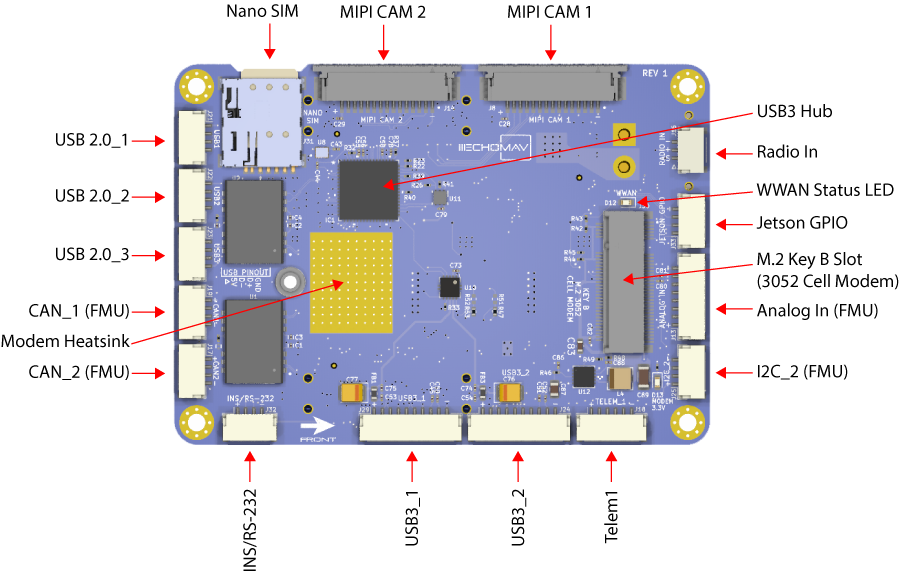
Nano SIM Card (J31)
A Nano SIM card holder. Used only if a M.2 3052 Key B Cellular modem is attached to J30.
MIPI Cam 2 (J14)
This connector provides a CSI/MIPI Camera connection, following the Raspberry Pi 15-pin 1mm spacing FFC standard.
Connector: J14, Part Number: 1-84952-5 Mating Connector: FFC Cable, 15 pos, 1mm pin spacing
| Pin Number | Direction | Voltage | Pin Description |
|---|---|---|---|
| 1 | Pwr | GND | GND |
| 2 | IO | Diff Signal | CAM1_D0- |
| 3 | IO | Diff Signal | CAM1_D0+ |
| 4 | Pwr | GND | GND |
| 5 | IO | Diff Signal | CAM1_D1- |
| 6 | IO | Diff Signal | CAM1_D1+ |
| 7 | Pwr | GND | GND |
| 8 | O | Diff Signal | CAM1_CLK- |
| 9 | O | Diff Signal | CAM1_CLK+ |
| 10 | Pwr | GND | GND |
| 11 | IO | +3.3V | CAM1_GPIO |
| 12 | O | +3.3V | CAM1_MCLK |
| 13 | O | +3.3V | CAM1_SCL0 |
| 14 | IO | +3.3V | CAM1_SDAO |
| 15 | Pwr OUT | +3.3V | +3.3V |
IPEX Connector (J24)
This connector provides a 4 Lane CSI/MIPI Camera connection, as well as USB3_2 and I2C. Specifically designed to be used with EchoMAV cameras, but can be adapter for other use cases where a fully shielded/flexible microcoax assembly is required.
Connector: J24, Part Number: 20682-030E-02 Mating Connector: EchoMAV IPEX Cable Assembly
| Pin Number | Direction | Voltage | Pin Description |
|---|---|---|---|
| 1 | Pwr | +5V | PWR OUT |
| 2 | Pwr | +5V | PWR OUT |
| 3 | Pwr | GND | GND |
| 4 | Pwr | GND | GND |
| 5 | NA | NA | NC |
| 6 | IO | +5V | USB VBus |
| 7 | IO | Diff Signal | USB D+ |
| 8 | IO | Diff Signal | USB D- |
| 9 | IO | Diff Signal | USB Rx+ |
| 10 | IO | Diff Signal | USB Rx- |
| 11 | IO | Diff Signal | USB Tx+ |
| 12 | IO | Diff Signal | USB Tx- |
| 13 | IO | +1.8v | I2C SCL |
| 14 | IO | +1.8V | I2C SDL |
| 15 | IO | Diff Signal | CAM0_D0- |
| 16 | IO | Diff Signal | CAM0_D0+ |
| 17 | IO | Diff Signal | CAM0_D1- |
| 18 | IO | Diff Signal | CAM0_D1+ |
| 19 | IO | Diff Signal | CAM0_CLK- |
| 20 | Pwr | Diff Signal | CAM0_CLK+ |
| 21 | Pwr | +3.3V | CAM0_GPIO |
| 22 | Pwr | +3.3V | CAM0_MCLK |
| 23 | Pwr | Diff Signal | CAM0_D2- |
| 24 | Pwr | Diff Signal | CAM0_D2+ |
| 25 | Pwr | Diff Signal | CAM0_D3- |
| 26 | Pwr | Diff Signal | CAM0_D3+ |
| 27 | IO | +1.8V | CAM0_SCL0 |
| 28 | IO | +1.8V | CAM0_SDAO |
| 30 | NA | NA | NC |
| 30 | NA | MA | NC |
Radio In (J16)
This connector provides a optional radio input in to the autopilot. A wide range of radio protocols are supported. Please see here for example.
Connector: J16, Part Number: SM03B-GHS-TB(LF)(SN)
Mating Connector: GHR-03V-S
| Pin Number | Direction | Voltage | Pin Description |
|---|---|---|---|
| 1 | I | +3.3V | RC In |
| 2 | Pwr OUT | +5V | +5V OUT_22 |
| 3 | Pwr | GND | GND |
Jetson GPIO (J33)
Spare GPIO from the Jetson module.
Connector: J33, Part Number: SM04B-GHS-TB(LF)(SN)
Mating Connector: GHR-04V-S
| Pin Number | Direction | Voltage | Pin Description | GPIO (Xavier) | GPIO (Orin NX and Orin Nano) | Jetson Pin |
|---|---|---|---|---|---|---|
| 1 | IO | +1.8V | GPIO 02 | GPIO3_PQ.03 | GPIO3_PP.06 | 124 |
| 2 | IO | +1.8V | nMOD_SLEEP | NA | NA | 178 |
| 3 | IO | +1.8V | SLEEP/WAKE | GPIO3_PEE.04 | GPIO3_PEE.04 | 240 |
| 4 | Pwr | GND | GND | NA | NA | NA |
V/I Sense and Analog In (J13)
This connector provides dual voltage and current sense input, for use with off-board current sensor monitor(s). These signals should be scaled to 0-3.3V or damage may occur. Your autopilot firmware will allow you to enter scaling factors for proper display of voltage/current when ground control software. This connector also provides two spare analog inputs to the FMU.
Connector: J13, Part Number: SM08B-GHS-TB(LF)(SN)
Mating Connector: GHR-08V-S
| Pin Number | Direction | Voltage | Pin Description | STM32 Pin |
|---|---|---|---|---|
| 1 | Pwr | +5.0V | +5V Out | NA |
| 2 | I | +3.3V | Voltage Sense1 | PA0 |
| 3 | I | +3.3V | Current Sense1 | PA1 |
| 4 | I | +3.3V | Voltage Sense2 | PA2 |
| 5 | I | +3.3V | Current Sense2 | PA3 |
| 6 | I | +3.3V | Spare ADC 1 | PC4 |
| 7 | I | +3.3V | Spare ADC 2 | PA4 |
| 8 | Pwr | GND | GND | NA |
I2C 2 (FMU) (J25)
This connector provides a Pixhawk standard I2C connection from the FMU (I2C 2).
Connector: J25, Part Number: SM04B-GHS-TB(LF)(SN)
Mating Connector: GHR-04V-S
| Pin Number | Direction | Voltage | Pin Description |
|---|---|---|---|
| 1 | Pwr OUT | +5V | +5V OUT_1 1 |
| 2 | O | +3.3V | I2C_2 SCL (FMU) |
| 3 | IO | +3.3V | I2C_2 SDA (FMU) |
| 4 | Pwr | GND | GND |
Telem1 (J18)
This connector provides a Pixhawk standard TELEM connection from the FMU (TELEM1).
Connector: J18, Part Number: SM06B-GHS-TB(LF)(SN)
Mating Connector: GHR-06V-S
| Pin Number | Direction | Voltage | Pin Description |
|---|---|---|---|
| 1 | Pwr OUT | +5V | +5V OUT_1 1 |
| 2 | O | +3.3V | Telem1 TX |
| 3 | I | +3.3V | Telem1 RX |
| 4 | O | +3.3V | Telem1 CTS |
| 5 | I | +3.3V | Telem1 RTS |
| 6 | Pwr | GND | GND |
USB3_1 (J36)
This connector provides a USB3 SuperSpeed connection to the Jetson, via a TUSB8042 hub. Note that 1uF capacitors are placed near the connector on the Tx+ and TX- lines.
Connector: J36, Part Number: Molex 105450-0101 Mating Connector: USB-C Cables/Devices
INS/RS-232 FMU UART (J32)
This connector provides an RS-232 level shifted UART from the FMU for connection to an external device, such as an Inertial Navigation System (INS).
Connector: J132, Part Number: SM04B-GHS-TB(LF)(SN)
Mating Connector: GHR-04V-S
| Pin Number | Direction | Voltage | Pin Description |
|---|---|---|---|
| 1 | Pwr OUT | +5V | +5V_OUT4 4 g |
| 2 | IO | Diff Signal | RS232 TX, UART4 (FMU) |
| 3 | IO | Diff Signal | RS232 RX, UART4 (FMU) |
| 4 | Pwr | GND | GND |
CAN 2 (FMU) (J17)
This connector provides a Pixhawk standard CAN connection from the FMU (CAN 2). The EchoPilot AI main board has a 120 ohm termination resistor at the CAN transceiver (LTC2875).
Connector: J17, Part Number: SM04B-GHS-TB(LF)(SN)
Mating Connector: GHR-04V-S
| Pin Number | Direction | Voltage | Pin Description |
|---|---|---|---|
| 1 | Pwr OUT | +5V | +5V OUT_1 1 |
| 2 | IO | Diff Signal | CAN 2+ (FMU) |
| 3 | IO | Diff Signal | CAN 2- (FMU) |
| 4 | Pwr | GND | GND |
CAN 1 (FMU) (J19)
This connector provides a Pixhawk standard CAN connection from the FMU (CAN 1). The EchoPilot AI main board has a 120 ohm termination resistor at the CAN transceiver (LTC2875).
Connector: J19, Part Number: SM04B-GHS-TB(LF)(SN)
Mating Connector: GHR-04V-S
| Pin Number | Direction | Voltage | Pin Description |
|---|---|---|---|
| 1 | Pwr OUT | +5V | +5V OUT_1 1 |
| 2 | IO | Diff Signal | CAN 1+ (FMU) |
| 3 | IO | Diff Signal | CAN 1- (FMU) |
| 4 | Pwr | GND | GND |
USB2.0 #3 (J23)
This connector provides USB 2.0 connectivity from the Jetson SOM via a hub onboard the EchoPilot AI mainboard.
Connector: J23, Part Number: SM04B-GHS-TB(LF)(SN)
Mating Connector: GHR-04V-S
| Pin Number | Direction | Voltage | Pin Description |
|---|---|---|---|
| 1 | Pwr OUT | +5V | +5V VBUS (Protected 500mA) |
| 2 | IO | Diff Signal | USB3_D- (Jetson) |
| 3 | IO | Diff Signal | USB3_D+ (Jetson) |
| 4 | Pwr | GND | GND |
USB2.0 #2 (J22)
This connector provides USB 2.0 connectivity from the Jetson SOM via a hub onboard the EchoPilot AI mainboard.
Connector: J22, Part Number: SM04B-GHS-TB(LF)(SN)
Mating Connector: GHR-04V-S
| Pin Number | Direction | Voltage | Pin Description |
|---|---|---|---|
| 1 | Pwr OUT | +5V | +5V VBUS (Protected 500mA) |
| 2 | IO | Diff Signal | USB2_D- (Jetson) |
| 3 | IO | Diff Signal | USB2_D+ (Jetson) |
| 4 | Pwr | GND | GND |
USB2.0 #1 (J21)
This connector provides USB 2.0 connectivity from the Jetson SOM via a hub onboard the EchoPilot AI mainboard.
Connector: J21, Part Number: SM04B-GHS-TB(LF)(SN)
Mating Connector: GHR-04V-S
| Pin Number | Direction | Voltage | Pin Description |
|---|---|---|---|
| 1 | Pwr OUT | +5V | +5V VBUS (Protected 500mA) |
| 2 | IO | Diff Signal | USB1_D- (Jetson) |
| 3 | IO | Diff Signal | USB1_D+ (Jetson) |
| 4 | Pwr | GND | GND |
M.2 Connector for Cellular Modem (J30)
This is a Key B M.2 connector for use with a 3052 form factor cellular modem, such as the Sierra Wireless EM9191. The connector includes USB3.1 connectivity to the modem ( PCIe is not supported). Attach the modem using a M2x0.4mm x 3mm wafer head screw.
A heat pad under the modem provides the option for a heat sinking solution from the cellular modem. The following components can be used to build a heat sink:
Thermal Pad between the modem and Carrier Board: Panasonic EYG-T7070A15A (cut to fit):
14x14mm heatsink mounted on the Carrier Board: CUI HSB03-141406
Heatsink Adhesive: MG Chemicals 8329TFF-25ML
Connector: J29, Part Number: SM3ZS067U310ABR1200
Mating Connector: M.2 Key B Modem, size 3052